Lianggong provides project-specific tunnel formwork systems for concrete lining in road, railway, hydropower and utility tunnels. Each system is configured according to the tunnel cross-section, lining thickness, planned pour length, curve radius, gradient, concrete pressure, movement method and available construction space.
Underground tunnel lining formwork is designed to match the tunnel profile and support repeated concrete pours. Building tunnel formwork is a separate system used for repetitive residential, hotel and dormitory layouts, where walls and slabs are cast together in a single operation.
Tunnel formwork should be selected according to the type of structure being formed, the tunnel cross-section and the planned concrete lining method. Underground tunnel lining formwork and tunnel formwork used in building construction serve different purposes and should not be treated as the same system.
Road tunnel lining formwork must follow the required internal clearance, arch profile, lining thickness and planned pour length. A project-specific system may combine curved steel facing panels, supporting frames, working platforms and positioning or retraction components.
For non-standard tunnel sections, customized steel formwork can be developed from the approved cross-section drawings. The movement method, adjustment arrangement and supporting structure should be confirmed according to the construction sequence and available working space.
Railway and metro tunnel formwork requires accurate control of the tunnel profile and sufficient clearance for construction access. System selection should consider the tunnel cross-section, track-area requirements, reinforcement arrangement, embedded components and movement between concrete lining sections.
The formwork should be positioned and checked against the approved tunnel profile before each pour. Whether the system uses mechanical movement, hydraulic adjustment or lifting equipment must be determined through project-specific engineering design.
Hydropower tunnels may contain circular, horseshoe-shaped or other project-specific concrete lining sections. The formwork configuration should account for the tunnel gradient, lining thickness, concrete pressure, construction access and the planned sequence of pours.
Customized steel panels and supporting structures may be required for curved or changing sections. The final system should be designed from the approved tunnel drawings rather than selected only by tunnel diameter.
Utility tunnels, service passages and shafts may contain flat walls, roof slabs or rectangular sections. Depending on their dimensions and construction method, steel frame formwork may be used for regular wall sections.
Curved transitions, special openings and non-standard sections may require customized steel panels. Final selection should consider concrete pressure, access restrictions, lifting equipment and the required concrete finish.
Underground tunnel lining formwork is designed around the profile of a road, railway, hydropower or utility tunnel. It commonly uses steel panels and supporting structures arranged around an arched, circular or project-specific cross-section.
Tunnel formwork is used in building construction for repetitive cellular layouts where walls and slabs are cast in the same operation. Typical applications include residential apartments, hotels and dormitories with repeated room layouts.
Since their structural forms, construction cycles and lifting or movement requirements are different, the two systems should not be presented as interchangeable.
Depending on the project design, a tunnel lining formwork trolley may include the following components:
Curved Lining Formwork Panels
Curved panels form the tunnel crown and sidewall profile. They may combine H20 timber beams with film-faced plywood and are designed according to the required tunnel cross-section and concrete pressure.
Main Portal Gantry or Main Steel Frame
Main longitudinal beams, columns, transverse members and diagonal struts form the principal load-bearing structure and transfer the concrete and construction loads to the supporting base.
Hydraulic Lifting and Adjustment Assembly
Hydraulic cylinders, a power unit and control valves may be used for vertical lifting, lateral fine adjustment and formwork retraction.
Travelling Wheel System
Rail-mounted wheel assemblies allow the trolley structure to move between successive concrete lining sections.
Stop-end Formwork
Stop-end formwork closes the end of each concrete pour and may use adjustable or retractable components according to the joint design.
Working Platforms and Safety Guardrails
Working platforms provide access for positioning, inspection, concrete placement and formwork operations, with guardrails configured according to the project design.
Diagonal Struts and Load-transfer Bracing
Diagonal members stabilize the structure and transfer construction loads to the supporting base while improving resistance to overturning and movement.
The actual components and operating method must be confirmed according to the project drawings and the approved construction method.
A typical tunnel lining formwork cycle includes the following stages:
Move the trolley or supporting structure along the rails or designated travel route to the next lining section.
Clean and prepare the formwork surface.
Position and align the top and side formwork according to the approved tunnel cross-section, using hydraulic or mechanical adjustment components as applicable.
Check the reinforcement, embedded components, construction joints, stop-end formwork and other construction interfaces.
Secure and lock the system with the specified supporting and adjustment components before concrete placement.
Place and cure the concrete according to the approved construction plan.
After the concrete reaches the required stripping condition, release, lower or retract the formwork according to the approved operating procedure.
Inspect the completed lining section and the trolley or supporting system before starting the next construction cycle.
The actual sequence, release criteria and movement method must follow the approved project method statement.

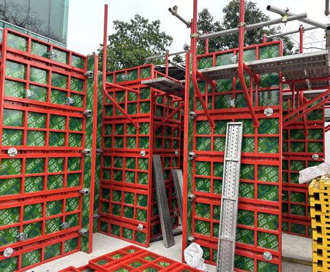
Lianggong supplied a tunnel formwork system for a building project in Uzbekistan. The system was configured for repetitive room layouts, allowing walls and slabs to be cast within the same construction cycle.
Project photos show the tunnel formwork system during different stages of site assembly and use. The formwork units were arranged according to the repeated room layout and repositioned as construction progressed.
The formwork dimensions, structural openings, stripping sequence and lifting arrangement were developed according to the project drawings and site conditions.

Lianggong supplied a hydraulic steel tunnel lining trolley for the Jakarta–Bandung High-Speed Railway project in Indonesia. The trolley was designed for 10.5 m concrete lining sections and consisted of steel formwork panels, a main gantry frame, a rail-mounted travelling system, screw jacks and a hydraulic positioning system.
During formwork setup, hydraulic cylinders raised and adjusted the top and side forms, while screw jacks and locking pins secured the system for concrete placement. After the concrete reached the required stripping condition, the forms were retracted hydraulically and the trolley moved along the rails to the next lining section.

Tunnel formwork selection should be based on the tunnel type, cross-section, lining thickness, planned pour length, movement method and site conditions. Underground tunnel lining formwork and building tunnel formwork serve different construction purposes, so each system must be configured according to its specific structural and construction requirements.
For a project-specific tunnel formwork recommendation, contact Lianggong with your tunnel drawings, lining requirements and planned construction method. These details help the engineering team determine the panel geometry, supporting structure, adjustment method and working-platform arrangement.